Raspberry Pi IoT Experiment #1: LDR and ThingSpeak HowTo
LDR (Light Dependent Resistors)
Light Dependent Resistors are also know as CdS cells (Cadmium Sulfide) are often used to measure illumination levels.
I used my DAQ testbed from my “Raspberry Pi Analog to Digital Conversion Experiments and Howto” article.
If you don’t have MCP3208’s, or high precision resistors, it is still possible to experiment with LDR’s using cheaper ADC’s:
- MCP3008 with 1% 10k resistors, sorted for 0.1% tolerance – this would give 0-8.192V with 8mV per bit
- inexpensive PCF8591 using 3.3v Vref, with 1% 10k resistors for voltage dividers giving a 0-6.6V range with 25.8mV per bit
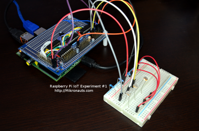
Here is a photo of my experimental setup:
(click on the image for larger version)
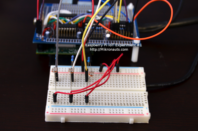
I added a breadboard with three LDR circuits:
- LDR + 1k pull down resistor
- LDR + 10k pull down resistor
- LDR + 100k pull down resistor
The LDR and the pull down resistor form a voltage divider.
- connect one end of the LDR to +3.3V or +5V
- connect the other end to an ADC channel, and to a pull down resistor
- connect the other end of the pull down resistor to ground
Here is a closer look at the breadboard setup:
(click on the image for larger version)
The LDR+1k signal should work best for allowing us to measure bright lights, as using higher resistor values will saturate more quickly, and be less capable of distinguishing between bright light levels.
The LDR+100k signal should allow is to see the greatest range of low light readings, and the LDR+10k signal should be a reasonable compromise in measuring light/dark ranges.
Which is best for you? It depends on the lighting level you are trying to measure, and on which (dark or bright range) is more important in your application.
Of course, none of these readings are calibrated at this time.
Dark Lab
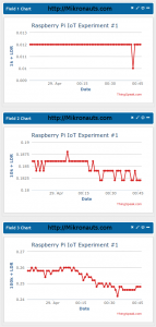
I logged some data around midnight, when the lights are turned off in the lab.
(click on the image for larger version)
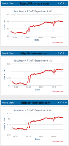
You can see that the LDR+100k result showed the greatest variance in readings in a dark environment.
The LDR+1k signal showed the least sensitivity to light levels in a dark room, and the LDR+10k was somewhere in the middle as far as low light sensitivity was concerned.
It is nice to see theory validated with experimental results!
Sunrise in the Lab
Let’s see how the light levels look in the lab during sunrise:
(click on the image for larger version)
You can clearly see that sunrise started just before 5:45am on the day the readings were taken, and that LDR+100k is the best choice for low light readings.
Can you tell when I turned my monitors on?
(two 32″ monitors, just behind the experimental setup)
(click on the image for larger version)
Bright Light Experiments
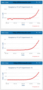
I used a 12 LED work light to force various light levels and show the effect of the various value pull-down resistors.
(click on the image for larger version)
I started with the work light turned off, then moved the work light relative to the LDR’s.
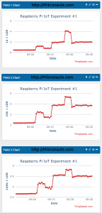
As you can see, LDR+1k would be able to measure even brighter light.
LDR+10k pretty much topped out from the 12 LED’s at close range.
LDR+100k also topped out, but note how much more room there is on the lower end of the scale to measure low light levels.
