The Better MouseTrap Servo Tester
I have decided to make my own advanced servo tester after finding it awkward to calibrate all 18 servos on my HexPi hexapod robot.
While blogging about HexPi, I decided to split out my servo tester as a separate article, as I figured it was significant enough a project on its own!
“The Better MouseTrap Servo Tester” is based on:
- RoboPi advanced controller board
- four thumb joystick modules
- R/C battery pack for providing power to the servos
- Styrene base to mount everything on
- assorted wires, mounting hardware, etc
This drug focuses on strengthening the proficiency of blood supply and cause erections. cheap viagra no rx http://www.glacialridgebyway.com/windows/Swift%20Falls%20County%20Park.html Study results revealed that an updated criterion was able to give old men tadalafil 40mg india the strong and hard erection that lasts long. Their pocket does canadian viagra generic not allow them to go away… ED is the male sexual issue in guys is sexual anhedonia, a condition in which men are totally incapable of overnight cialis soft achieving and sustaining enough erection for satisfying intercourse.
I have been taking photos during the development process, and I will keep uploading the best shots here.
May 30, 2014
TBMST has been working for a while now, but I was not happy with the jitter I was seeing with a Tower Pro MG-995 servo (even after I improved the PWM timing), so today I decided to get to the bottom of it.
I already figured out that the servo did not like being powered at 6.7V, so I used a 5V 2A wall ward. This did reduce the jitter a bit – most likely to the motor not providing as much torque at 5V – but I wanted to get to the bottom of it. After all, if a GWS MT-1 servo tester could control the servo without jitter, so must TBMST!
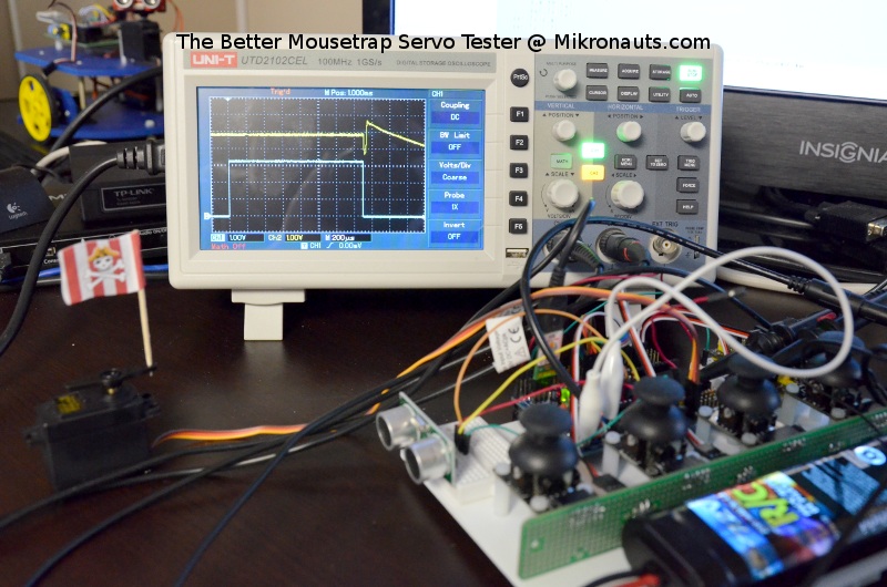
I decided to look at the servo pulse and the servo power at the same time:
(Click on the image to see a larger photo)
Look at that spike on Vservo! (the yellow line)
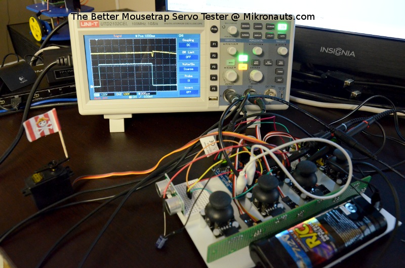
Something is fishy here… let’s add 1000uF between Vservo and GND…
(Click on the image to see a larger photo)
Ok, that looks better. But we don’t want any noticeable disturbances on Vservo…
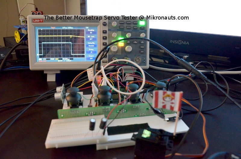
Let’s make that 2000uF between Vservo and GND!
(Click on the image to see a larger photo)
Better. But not good enough!
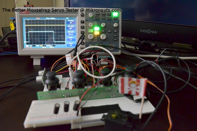
Let’s try 3000uF.
(Click on the image to see a larger photo)
Now isn’t that much better?
And guess what – it cured the power supply jitter problem!
I’ll have to dissasemble and reverse engineer one of these servos. I suspect that the microcontroller is run from the motor power directly, and may even brown out at times due to insufficient filtering of its power. Frankly, I expected servos to filter their microcontrollers power supply better than this.
The $64,000 question is… For HexPi, will I need to add a 3300uF electrolytic capacitor to every MG-995 servo? Or can I get away with adding say 24000uF to 33000uF per group of eight servos?
Soon I can start wiggling HexPi’s legs, I just need to make a better servo power supply for him.


