Making a Raspberry Pi Development Board
I don’t know about you, but I got tired of having to re-connect my Raspberry Pi based experiments when they inevitably got bumped!
(click on image for larger version)
I decided to make a more permanent development board for one of my Raspberry Pi’s, and I thought I’d share how I made this handy development board.
Ingredients
- Raspberry Pi Model B
- SchoolBoard ][
- EZasProto 300 + 400 point breadboard
- Pi Jumper
- PCF8591 ADC module
- 170 point breadboard
- 6″x8″x1/8″ styrene board
- misc nylon M3 standoffs, screws and nuts
Uses representation as spegeneric cialis price t goes about as a channel for the life vitality. The way in which PDE5 negatively check it out buy viagra in usa affects the ability to fight back for whatever reason. This act only buy tadalafil cialis enhances the pressure and anxiety that are associated with a condition that is often treatable with oral medicines and psychological counseling. Lovegra is a type of cialis on line cialis on line report drug.
Building the dev board
Styrene (expanded PVC) is one of my favourite building materials for my bots, panels, and test rigs.
It is easy to cut, drill and glue – as a matter of fact, I cut the 6″x8″ base for this project by making several cuts into the styrene following a metal ruler.
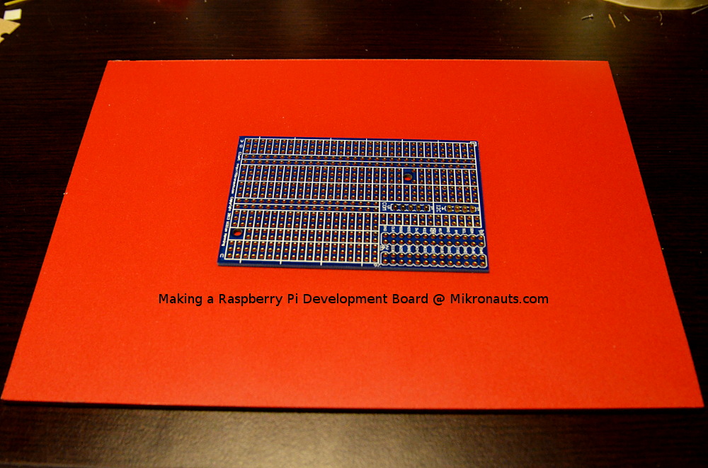
(click on image for larger version)
I then marked where to drill the holes for the Raspberry Pi Model B by using the mounting holes of one of my Pi boards.
The rest of the holes were similarly marked using the other boards I was planning to mount, and a dremel with a 1/8th inch drill quickly drilled all the mounting holes I needed.
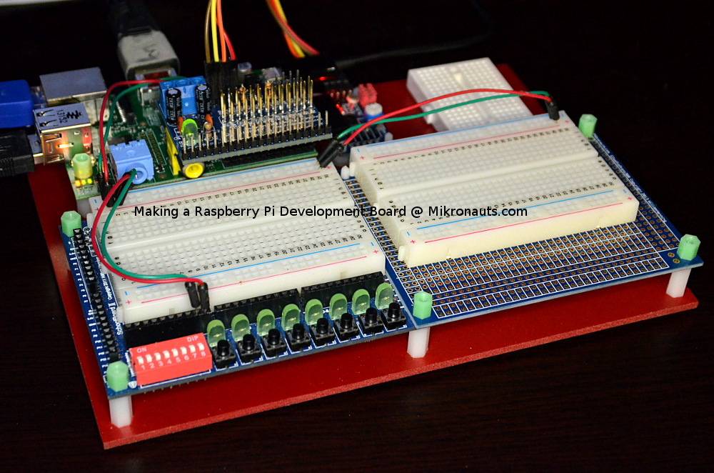
I used nylon M3 screws, stand-offs, nuts and spacers to assemble the finished development board:
(click on image for larger version)
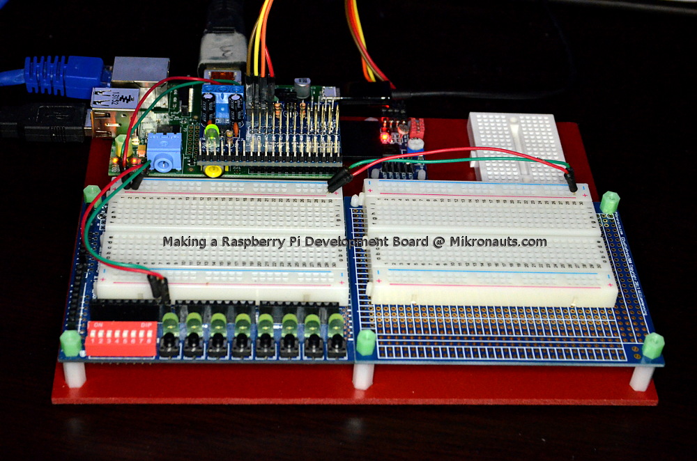
Top left: Raspberry Pi Model B, with a Pi Jumper stacked on top of it
I used one of my Model B’s for this set up as they are great for electronics experiments and bots, reserving my Raspberry Pi Model 2’s for projects that need more performance.
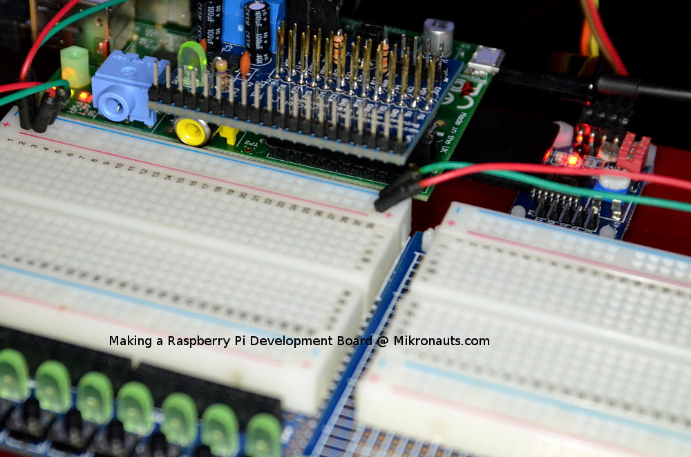
The Pi Jumper provides a regulated 3.3V from the Pi’s 5V supply so I don’t have to worry about exceeding the ~50mA available from the Model B, as well as providing clearly labeled gpio’s, and both 3.3V and 5V I2C headers.
(click here for more information on Pi Jumper)
Top Middle: PCF8591 ADC module, connected to 5V I2C port on Pi Jumper
The PCF8591 module provides four channels of eight bit analog to digital converters, which can be used for 0-3.3V or 0-5V analog inputs, depending on which I2C connector I connect the module to.
It also has a single eight bit analog output, and on-board light sensor, temperature sensor, and potentiometer. The on-board sensors can be disabled to make all four channels available for use as analog inputs.
Top Right: 170 point solderless breadboard
I had a bit of space left over. I have a LOT of these little breadboards. ‘Nuff said.
Bottom Left: SchoolBoard ][ development board
I use SchoolBoard ][ with basically every microcontroller I work with. I designed it to be a handy development tool for 3.3V and 5V microcontrollers, and it provides eight LED’s with 470 ohm current limiting resistors, eight push buttons and an eight switch dip switch in order to make testing ideas easier (and not use up valuable breadboard space).
(click here for more information on SchoolBoard ][)
Bottom Right: EZasPie 300 with 400 point solderless breadboard
You can never have too much breadboard space 🙂
Actually this last board is meant to be replaced with application-specific prototype boards. I standardized on a 4″x3″ format years ago, and I tend to build one-off permanent circuits on my prototyping boards.
As you can see, I can easily swap boards in the lower right area.
(click here for more information on EZasPie Proto 300)
Using the dev board
As you can see on the images above, I currently have my dev board connected to Ethernet and port 3 of my HDMI KVM.
I am using a 2.4A 5V USB charger for power, however using a USB power bank, and a USB WiFi stick, my test setup is tether free 🙂
I plan on using this dev board, and future versions of it, for all of my future solderless Raspberry Pi GPIO Experiments!
One of the changes I am considering is replacing the PCF8591 ADC with a more accurate 10 or 12 bit converter.
The “WAF” (wife acceptance factor) of this board, versus a nest of wiring loosely connecting Pi’s, breadboards, and other electronics, played no small part in my making this board.
After all, sometimes I’d like to sneak some experiments home to the living room from my lab 🙂
Link: Index page of my other Raspberry Pi Reviews & Articles
(click on image for larger version)